Thanks to Bruce C. from Fairbanks for helping me with the measurements on this page – he kindly transferred his measurements to paper and mailed them to me. Unfortunately they got lost in the mail for a while, and then I took them to my basement, which promptly flooded. I thought the paper was ruined, but eventually I was able to dry it out and peel it apart. Thanks, Bruce! (All measurements and errors are my own.) – Matt
Note: I think newbies will find this page confusing and possibly discouraging. If you’re working on your first DIY Packraft without the help of someone who has made one before, I recommend revisiting this page after your packraft is complete (i.e. skip this stuff until then, as it will make more sense once you’re familiar with the terms and how things fit together). You also don’t need to install any or all of these attachment points – it’s a matter of personal preference, depending on what type of paddling you like to do. The attachment points shown below are for a whitewater paddling setup, including perimeter grab lines/gear tie-downs, thigh straps, back band, and a foot rest (similar to Dom’s and Eliot’s setups); however, many people will be fine with just a single attachment point for a drybag or something in between.
Note: All measurements are for the V3 single-person packrafts (all sizes).
“Tie-downs” (a.k.a. “attachment points” – I use these terms interchangeably) can be installed either before or after your packraft is built. It’s easier to heat seal them to the tube fabric before everything is put together, but unfortunately it’s difficult to figure out where to locate them if you don’t already have some reference points to work from. This page provides some measurements you can use to locate attachment points like those in the diagrams below. The measurements are approximate – the exact locations aren’t critical – but if you’re going to move things around, first think about how they will interact with your paddle stroke and anything else you want to add to your packraft (such as a spray deck or harpoon turret). This page shows how to make several different styles of attachment points.
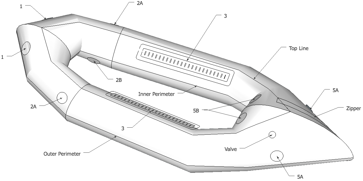
To help you figure out where to attach something I haven’t shown below, I’ve also given measurements for locating the packraft’s outer perimeter, inner perimeter, and top line (the “top line” passes through the highest points on the tubes). Again, these are approximate measurements.
When placing a circular tie-down, try to orient it so that the strongest dimension is aligned with the direction you expect will experience the strongest pull when you’re out on the water. This isn’t super critical – just do your best to visualize what will be tied to it and which direction it will be pulled, and then rotate the circle to minimize twisting on the loop or D-ring attached to it.
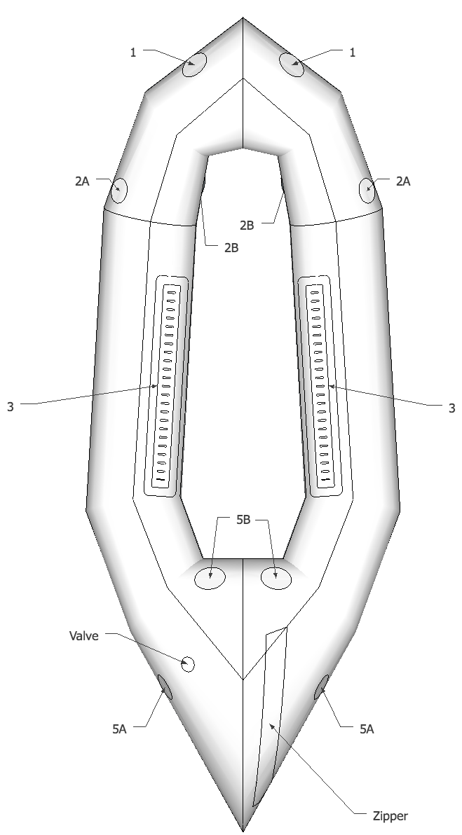
Here’s a key to the following diagrams and text:
- Circles 1, 2A, and 5A (left and right) are simple gear tie-downs and/or attachment points for grab lines.
- Circles 2B (left and right) are attachment points for a foot rest and/or thigh straps.
- Circles 5B (left and right) are attachment points for a back band or inflatable back rest.
- Strip 3 (left and right) can be used to attach a back band and adjustable thigh straps.
- You can also add attachment points to the floor or anywhere else you choose (not shown).

Click to zoom.
Attachment Point Locations, measurements from ends of tube pieces (approximate):
- Location 1 – centered 27 cm (10 1/2″) from the center of the wide end of piece #1, and midway between the two curved edges.
- Location 2A – centered 31 cm (12″) from the wide end of piece #2 (measure perpendicular to wide end), and about 8 cm (4″) from the straighter of the two curved edges.
- Location 2B – centered 13 cm (5″) from narrow end of tube piece #2, and 10 cm (4″) from the straighter of the two curved edges.
- Location 3 – centered about 35 cm (13 3/4″) from the narrow end of tube piece #3, parallel with the straight edges, and positioned close to the seam between tube pieces #3 & #4 (leave at least 2.5 cm / 1″ between it and the edge of the tube piece so it will not interfere with the seam strip)
- Location 5A – centered 23.5 cm (9 1/4″) from the wide end of piece #5 (measure perpendicular to the edge), and 24 cm from the shorter of the two curved sides
- Location 5B – centered 35 cm (13 3/4″) from the narrow end of piece #5, and midway between the two curved edges
- Check the zipper installation and Boston valve installation pages for their locations
Inside Perimeter, approximate position on tube pieces 1-5:
- Tube piece #1: 22 cm (8 1/2″) from the narrow end of piece #1
- Tube piece #2: 17.5 cm (7″) from the narrow end of piece #2
- Tube piece #3: 19 cm (7 1/2″) from the narrow end of piece #3
- Tube piece #4: 19 cm (7 1/2″) from the narrow end of piece #4
- Tube piece #5: 21 cm (8 1/4″) from the narrow end of piece #5
Top Line, approximate position on tube pieces 1-5:
- Tube piece #1: 39 cm (15 1/4″) in a straight line from the rearward corner of the narrow end of piece #1 to a point on the straighter of the two curved sides, and 48 cm from the forward corner of the narrow end of piece #1 to a point along the curvier of piece #1’s two curved sides
- Tube piece #2: 40 cm (15 3/4″) from the narrow end of piece #2
- Tube piece #3: 41 cm (16″) from the narrow end of piece #3
- Tube piece #4: 42 cm (16 1/2″) from the narrow end of piece #4
- Tube piece #5: 40 cm (15 3/4″) from the narrow end of piece #5 to a point on the shorter of the two curved sides, and 60 cm (23 3/4″) from the narrow end of piece #5 to a point along the longer of the two curved sides
Outside Perimeter, approximate position on tube pieces 1-5:
- Tube piece #1: 20 cm (8″) from the aft corner of the wide end of piece #1 to a point on the straighter of the two curved sides, and 30 cm (12″) from the forward corner of the wide end of piece #1 to a point along the curvier of the two curved sides
- Tube piece #2: 58 cm (23″) from the narrow end of piece #2
- Tube piece #3:
- Tube piece #4: 20 cm (8″) from the wide end of piece #4
- Tube piece #5: 18 cm (7″) from the wide end of piece #5
If you have comments or questions, please post them below!
4 Comments
CW · May 15, 2018 at 1:13 pm
“Tube piece #1: 39 cm (15 1/4″) in a straight line from the narrow end of piece #1 to a point on the straighter of the two curved sides, and 48 cm from the narrow end of piece #1 to a point along the curvier of piece #1’s two curved sides.”
Does this straight line start from the center or the corner of the narrow piece or another point?
Matt (Admin) · May 15, 2018 at 2:01 pm
In this case it’s from the nearest corner (the two ends). I’ll try to clarify that in the text.
CW · May 16, 2018 at 8:21 pm
Thank you. This is a great guide for getting an approximation for where things will end up on the boat. Just FYI – the 2A measurements are missing.
Matt (Admin) · May 17, 2018 at 9:34 am
Thanks for pointing that out! I’ve added 2A now.