Follow the steps in this video to install the Boston valve in either tube 4L or 4R. Which side you choose doesn’t really matter, but if you’ve installed a zipper in one of these tubes, install the valve in the other tube.
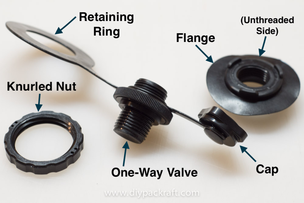
The parts of the heat sealable Boston valve. Only the flange is permanently attached to the packraft.
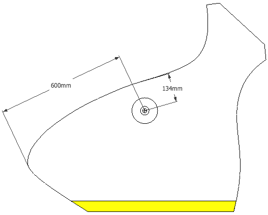
Boston valve location as shown in the demo video (in either tube 4L or 4R), centered about 13.5 cm (5 5/16″) from the rear center seam and 60 cm (24″) from the rearmost part of the tube fabric (image not to scale). The exact placement of the valve isn’t critical, but this location is convenient to access and will not interfere with a spray deck or the rear center seam strip. (Drawing not to scale.)
Advanced Option: To increase airflow through the inner one-way “check valve” portion of the Boston valve, you can temporarily remove the circular silicone flap and then drill out the five air holes to make them larger, and then insert the silicone flap back in place. Only do this if you understand how the check valve works and are comfortable using a drill on this critical part of the valve.
0 Comments